hardware
Hardware
The car comes with several hardware components that need to be connected. This page provides an overview and delves into more detail about each component, including datasheets.
Servo
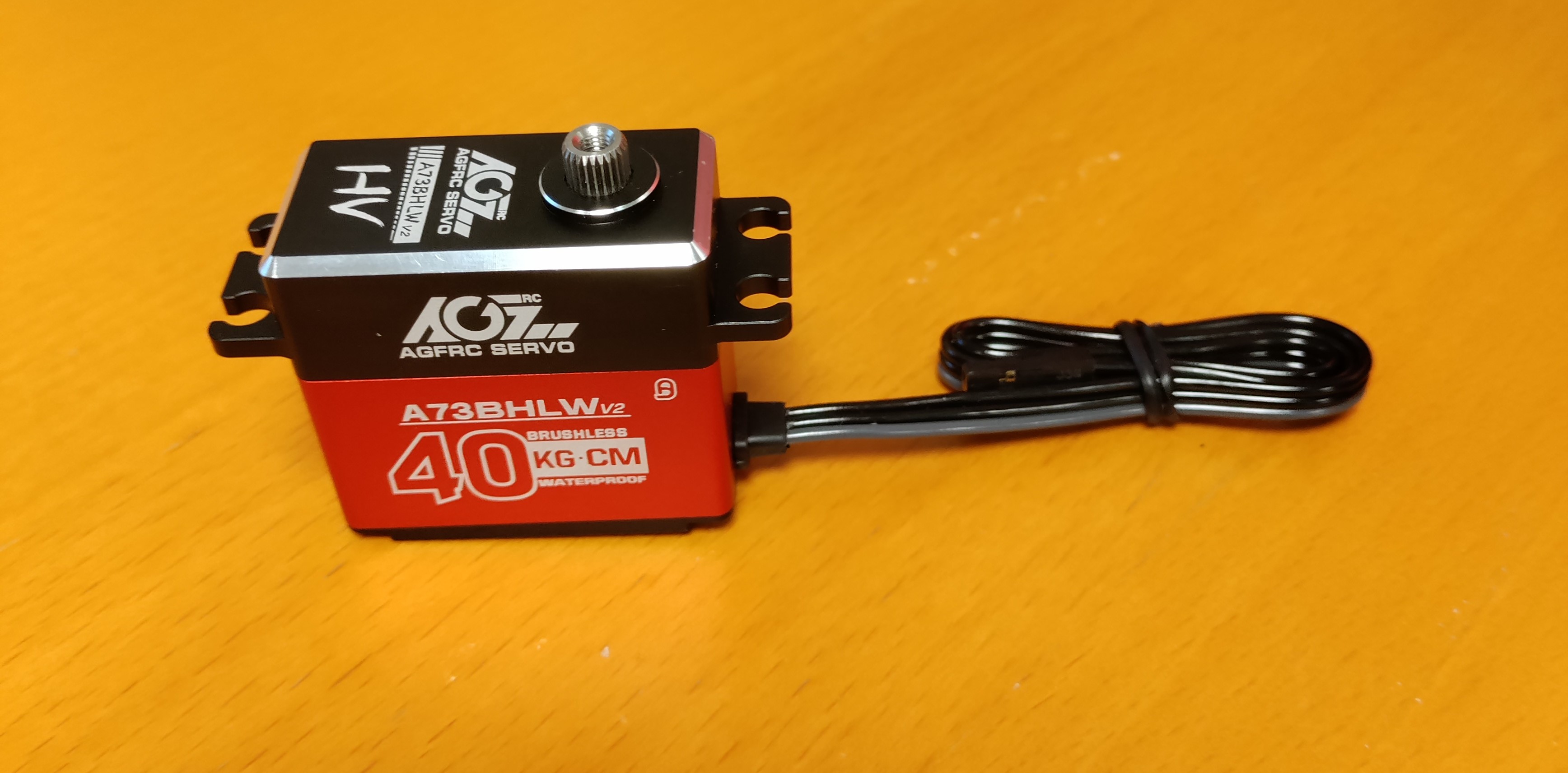
The Servo data sheet provides information about the servo, which is used for steering the car’s wheels. The servo receives a PWM signal from the servo board to accomplish this. Here’s an image of the component:
Motor
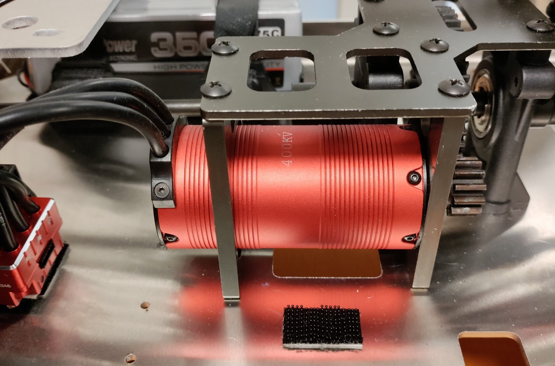
The motor comes pre-mounted on the car. The Motor data sheet provides additional information about the motor.
Here’s an image of the motor:
Electronic Speed Controller (ESC)
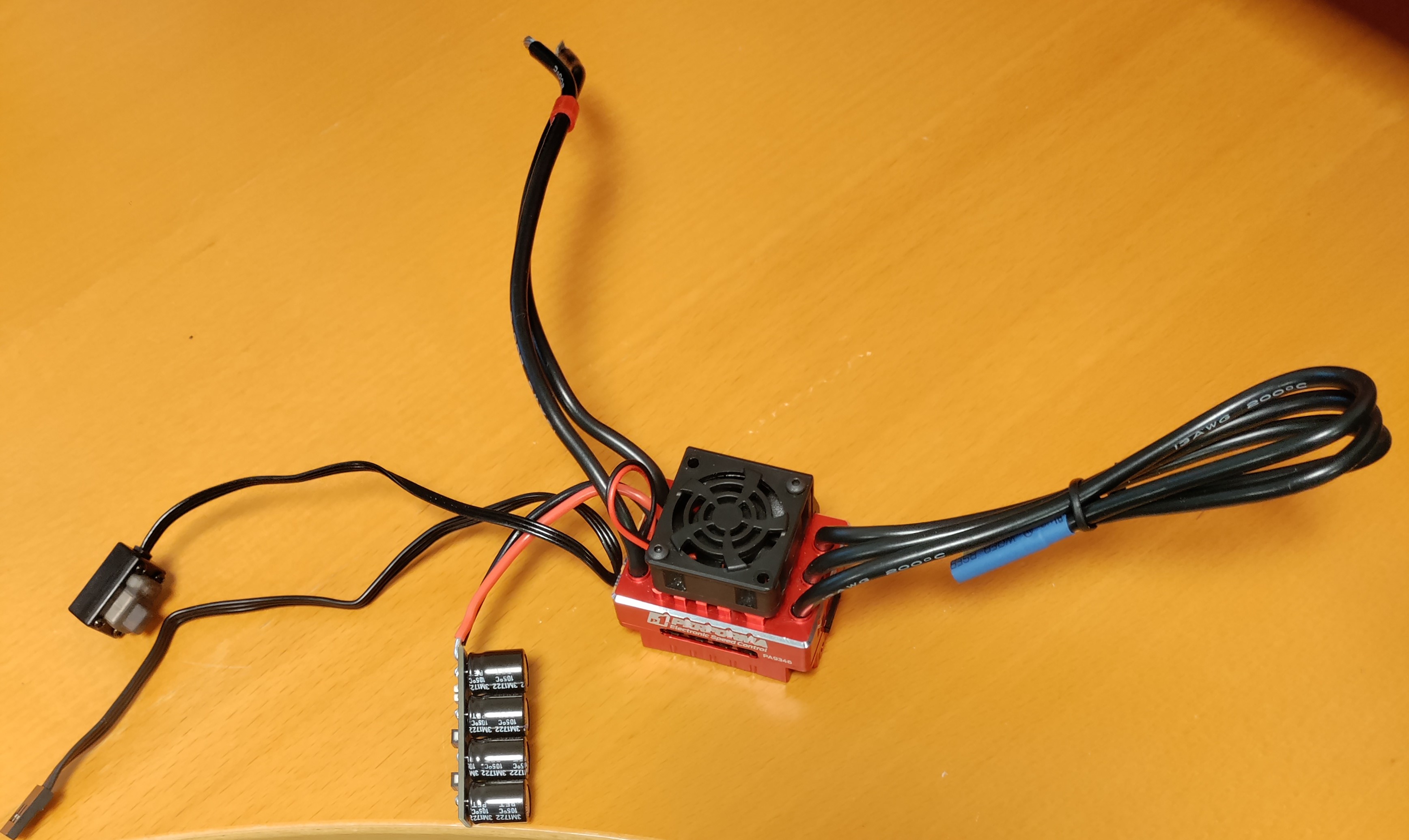
The ESC data sheet offers details about the Electronic Speed Controller (ESC). The ESC controls the car’s motor and requires three-phase current to function. The ESC has multiple inputs, including three cables for the motor’s phases, a two-wire input for battery connection, and an input for the steering signal. The power input features a Battery Elimination Circuit (BEC) to regulate voltage to 6V/7.4V and 4A when connected to a 2-4 cell battery (7.4-14.8V). This ensures proper and regulated voltage for connected electronics. However, the motor’s performance still depends on battery voltage. For optimal performance, a 4-cell battery providing 14.8V is recommended for the Rover.
Here’s an image of the ESC:
The ESC also has tunable parameters that can be programmed using a setup button or a program box connected via USB to a computer, as shown in the image below:
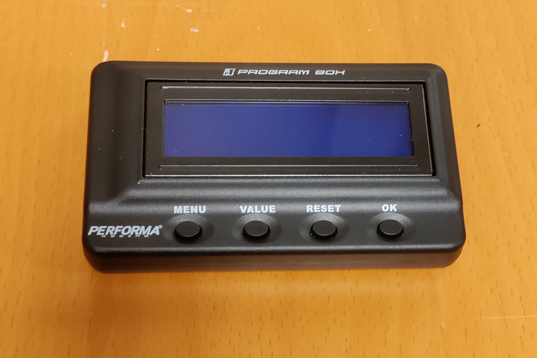
Check out the video below on how to program the ESC using the Performa programmable box to set parameters:
Radio Receiver
The Radio Transceiver data sheet is available for the radio receiver. This receiver captures radio signals, similar to how radio cars work in the hobby market. The red box in the image below indicates where channels are displayed. The data sheet provides information about the functionality of each channel. For steering the car, channel one controls the servo, and channel two controls the motor.
Here’s an image of the radio receiver:
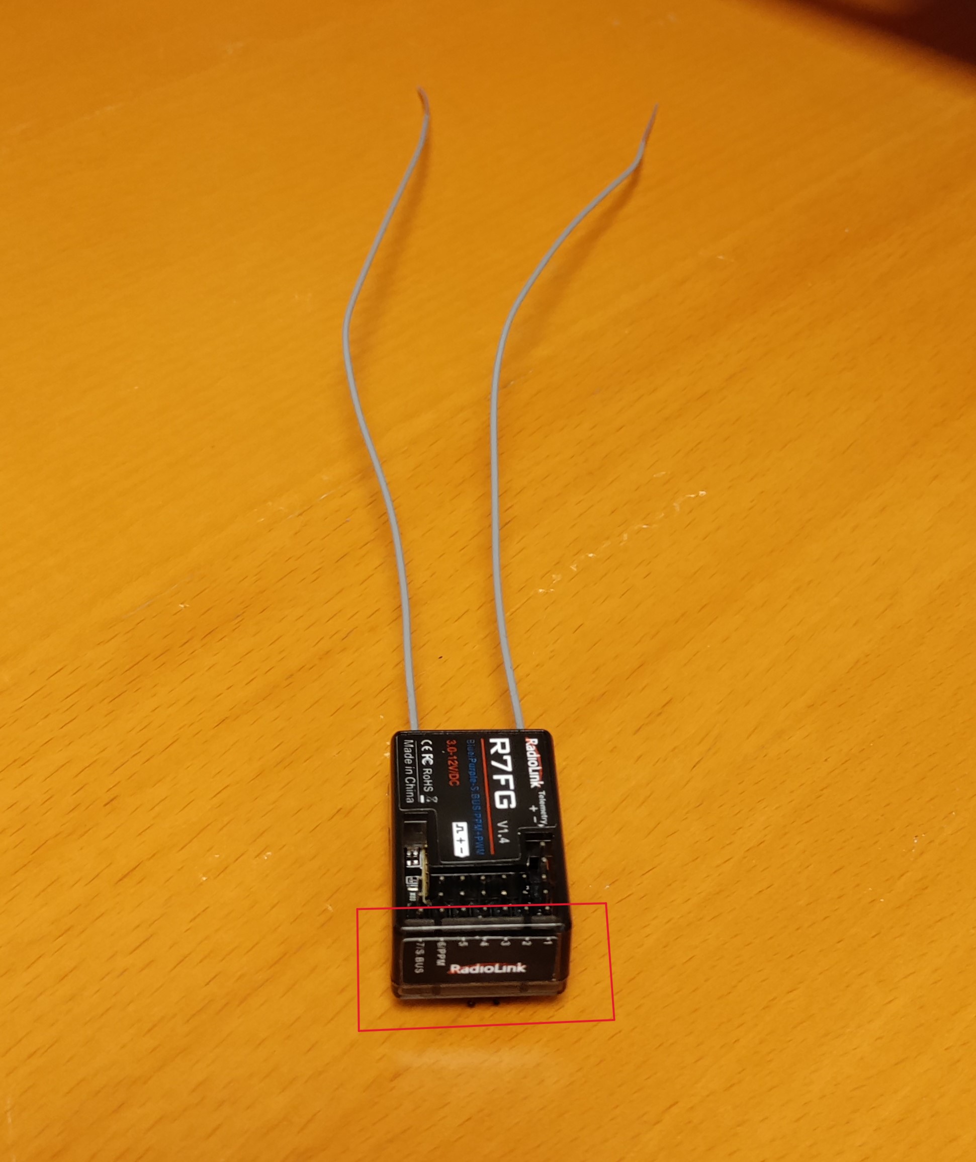
When using the radio receiver for steering, consider the following:
To ensure the best signal reception, keep the antennas at a 90-degree angle relative to each other. This allows reception of both vertical and horizontal signal polarizations without loss of information.
Protect the receiver from water if operated in rainy conditions. Wrapping it in a plastic bag is a simple way to shield it. Water entering the receiver can lead to uncontrolled steering. Consider using isolating material to protect it from vibrations, given its sensitive electronic components.
Metallic parts and other electrical components on the car could interfere with the signal. If the signal seems weak, consider mounting the receiver in a more isolated position.
Servo board
The servo board is a general-purpose control module that can be used to control servos or electronic speed controllers (ESCs). It has a PWM output with voltage and current measurement, an H-bridge motor driver for controlling brushed motors, and sensor input. Additionally, it has an I2C port and an SPI port. A picture is shown below of the two identical cards.
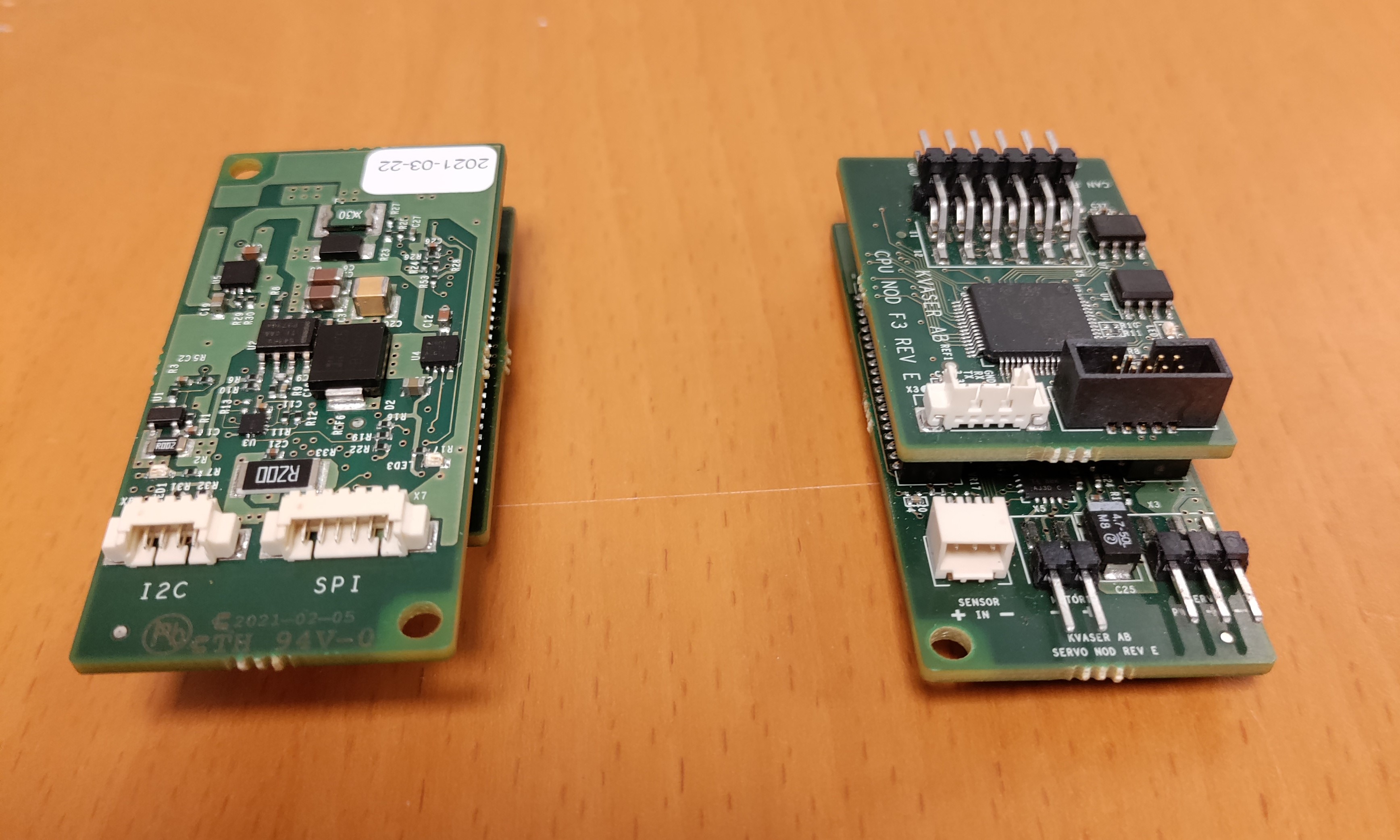
One of the reasons the servo board is a necessity is that many components use PWM signals as input to function. The car however uses the CAN protocol to send messages to the ECUs in the system. This means that there needs to be a way to convert CAN messages to PWM which is the main function of the servo board. The module consists of two separate boards mounted which are the CPU and servo board. To understand its required inputs and outputs let us start by looking at the servo board circuit schematic which is shown below.
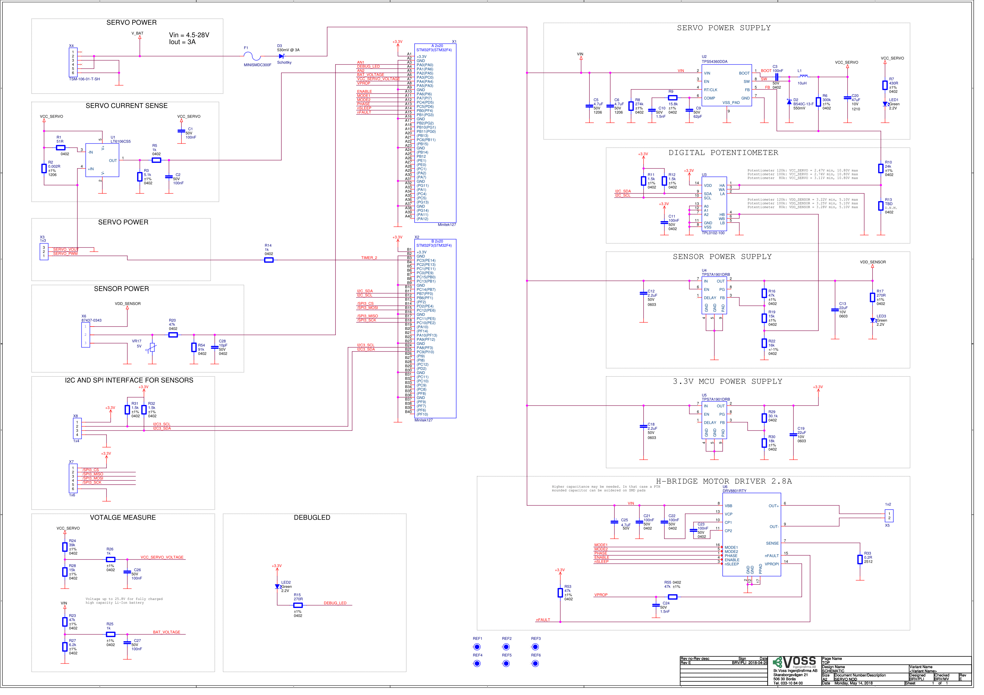
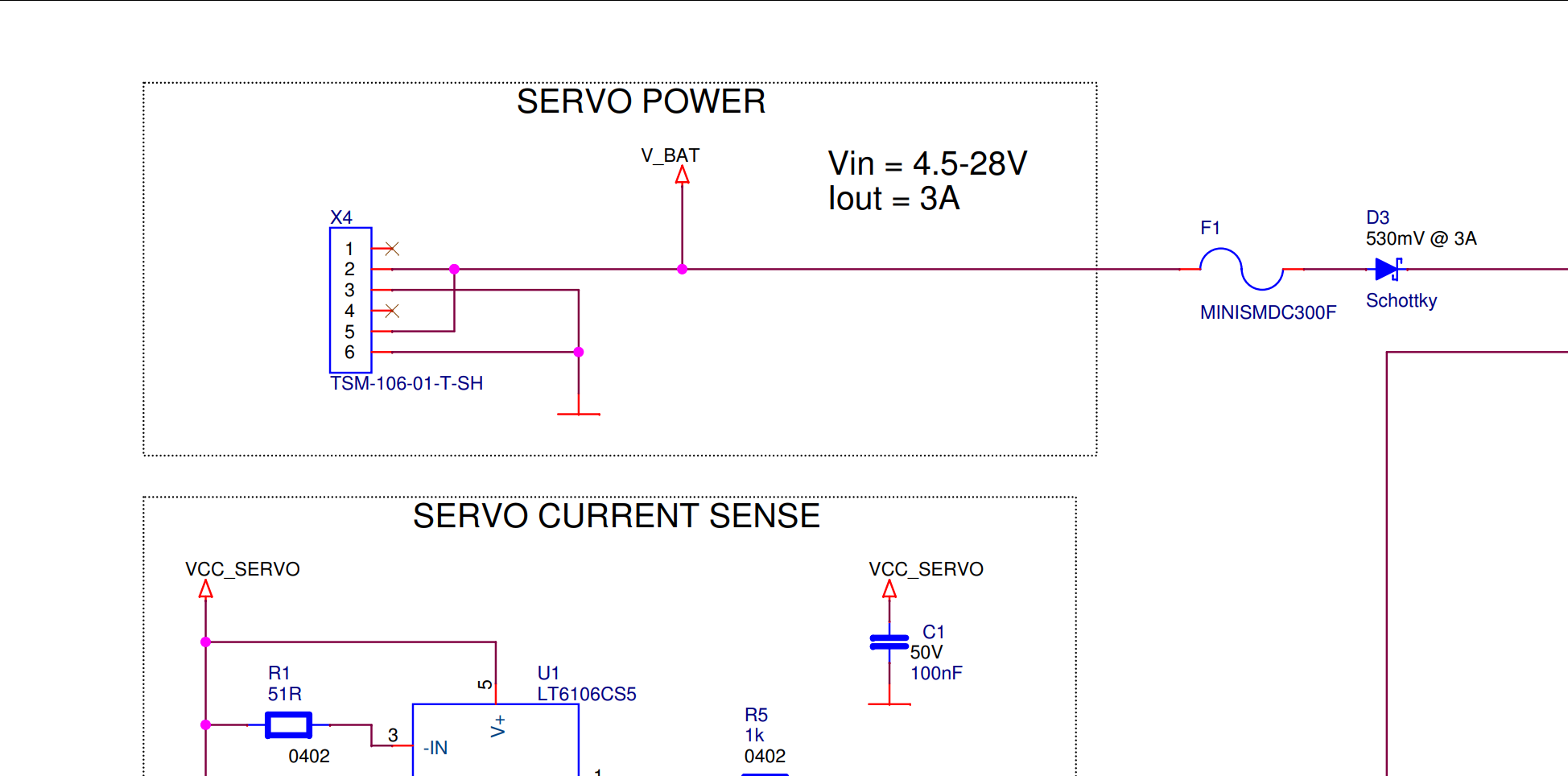
There are a lot of details here but the only things we need to worry about are certain ports that serve as either an input or an output. The schematic has labels associated with a corresponding port on the board. These labels are named with an X followed by a number for instance port X4 is located at the upper left corner of the schematic and can also be located on the actual circuit board at location X4. A zoomed-in figure is shown below. This gives an idea of how to connect the ports by looking at the schematic, for instance, we can see that ports 1 and 4, 2 and 5 and 3 and 6 lead to the same connection suggesting a parallel circuit that can be used to connect other components over the same voltage or that require the same signal. This port is used to supply power to the servo board and since there are 6 pins, other components can be connected through this node that require power from the battery. Note also that pins 1 and 4 have dead ends meaning that they do not perform any particular function other than ensuring that standard 3-pin connectors can be connected to the port. The circuit is designed to handle an input voltage between 4.5-28 V and up to 3A, there exists circuitry to prevent overcurrent.
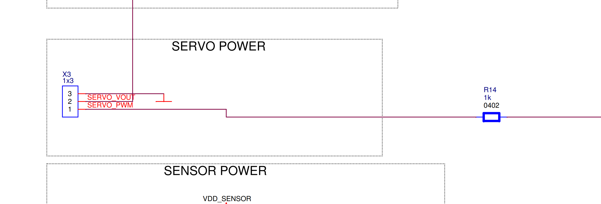
Similarly, a zoomed-in version of the servo module output at port X3 can be seen in the figure below. The way to see this port as an output and not an input is that the servo modules function is to convert CAN messages to PWM and since the labels of the ports are ground, SERVO VOUT and SERVO PWM suggesting this port needs to be connected to an external component requiring PWM like the ESC or the servo. There are some other ports as well but they are not required for a basic start-up of the car.
It is now time to look at the upper board of the servo module which is the CPU board, the circuit schematic is shown below.
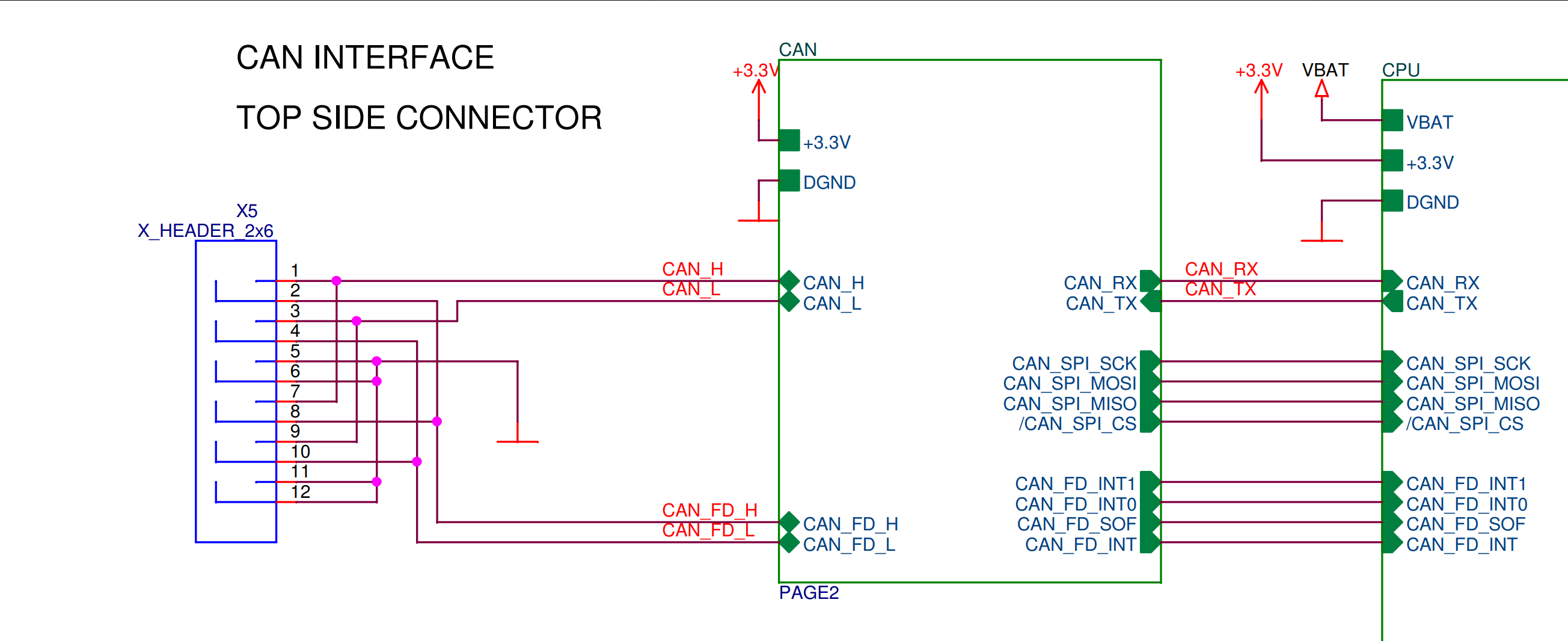
The important part of this schematic is port X5 which can be seen zoomed in below. The inputs required for this port are the CAN messages that need to be converted to PWM signals. As can be seen, there are 12 pins in total, and half of them are connected to the same buses similar to the power input for the bottom board. Note that the pins are connected to two different inputs in the sense that the odd numbers 1,3,5,7,9,11 lead to the commonly used CAN protocol input while the even numbers 2,4,6,8,10,12 lead to an alternative input using the CAN FD protocol. For a basic CAN setup, use the odd numbers to use the standard CAN protocol where pins 1,3,5 and 7,9,11 can be used. The CAN FD protocol is an alternative way of using CAN that can handle larger data rates but it is not necessary. Other functions can also be utilized on the servo board such as connecting external sensors for instance but this is not required.
IO board
The IO board is a general-purpose board for applications utilizing IO devices. It has ports for connecting switches, GPIO devices and analog devices, as well as an I2C port and an SPI port.
Two reference applications are using the IO module, an SBUS receiver application and an application utilizing joysticks.
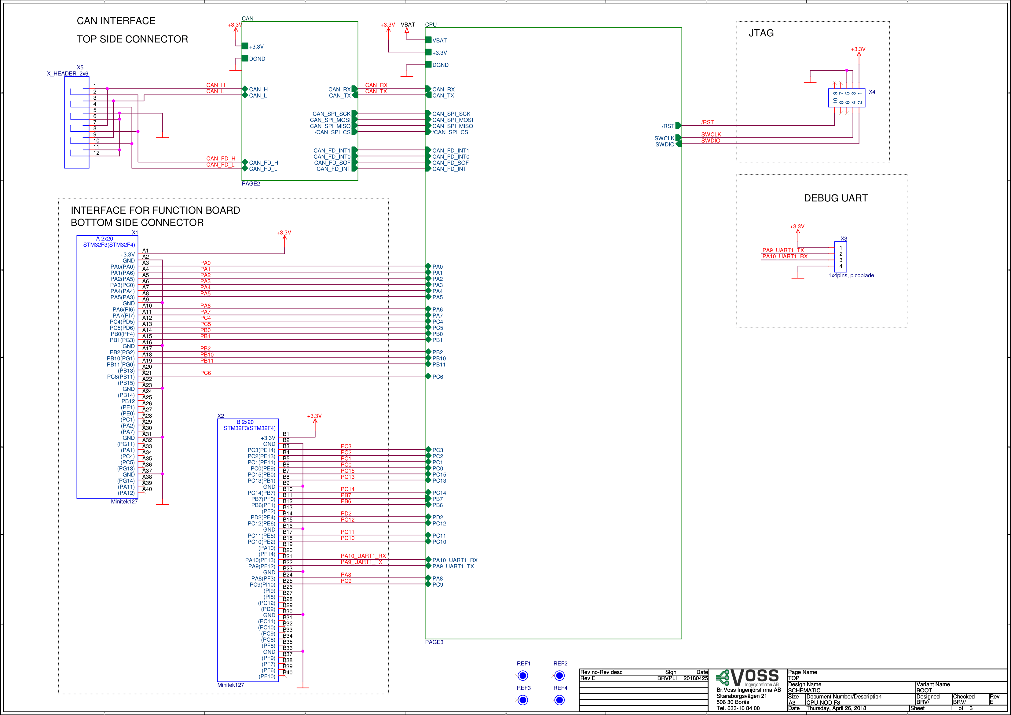
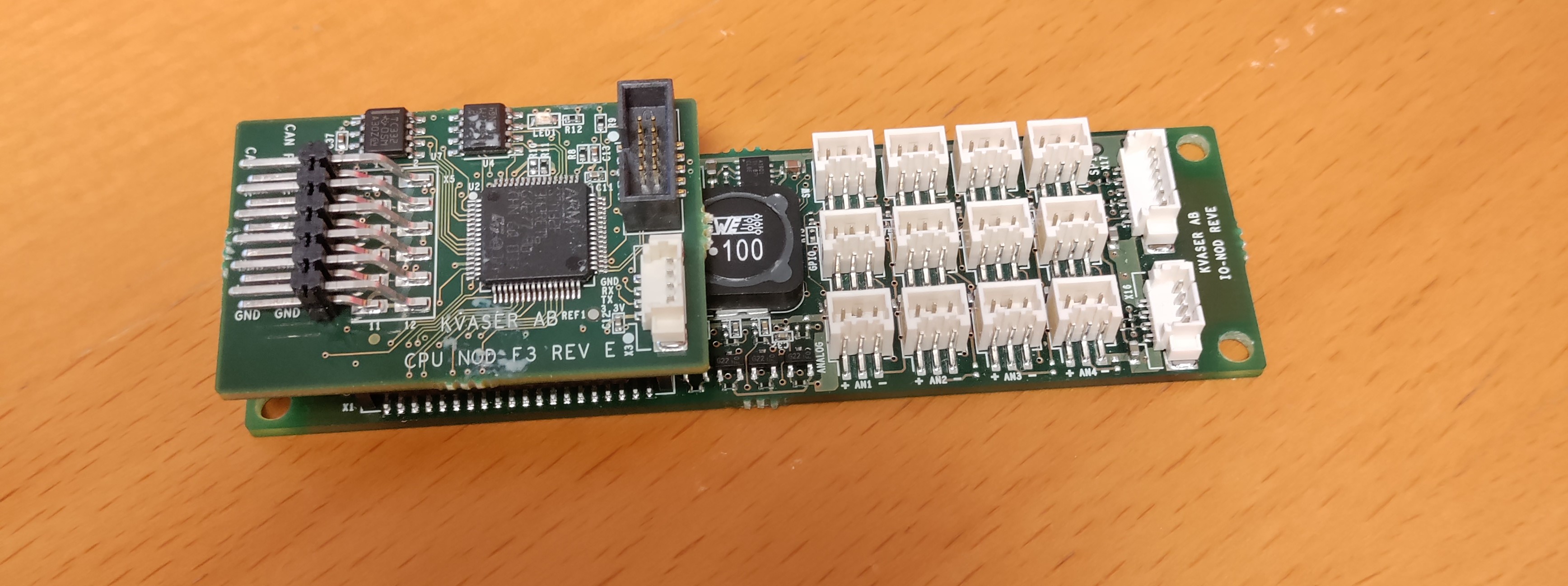
The IO-board can be used in the car to control it through radio waves for example. The circuit schematic can be seen below. Together with a picture of the component. Note that the figure shows the IO board equipped with the CPU board on top.
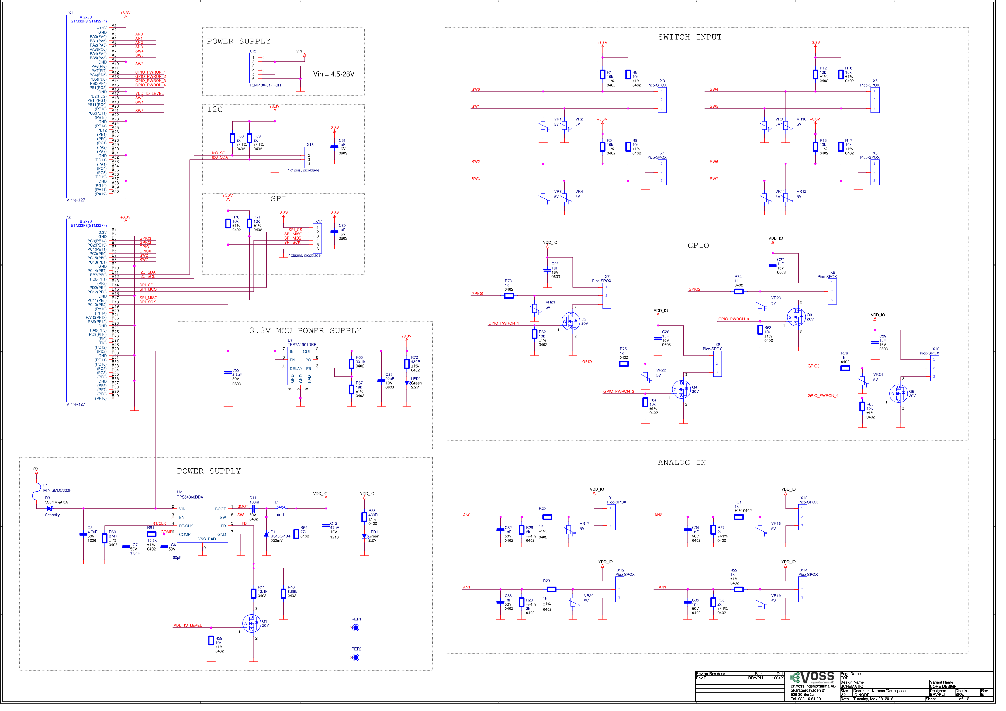
To connect this circuit to power, let us take a closer look at the power supply shown below. As can be seen, there are six pins in total where pins 1 and 4, 2 and 5, and 3 and 6 connect to the same internal bus. Since this is the power supply, pins 1 and 4 are useless and are not needed except to connect standardized connectors called Dupont connectors that use three pins to the port.
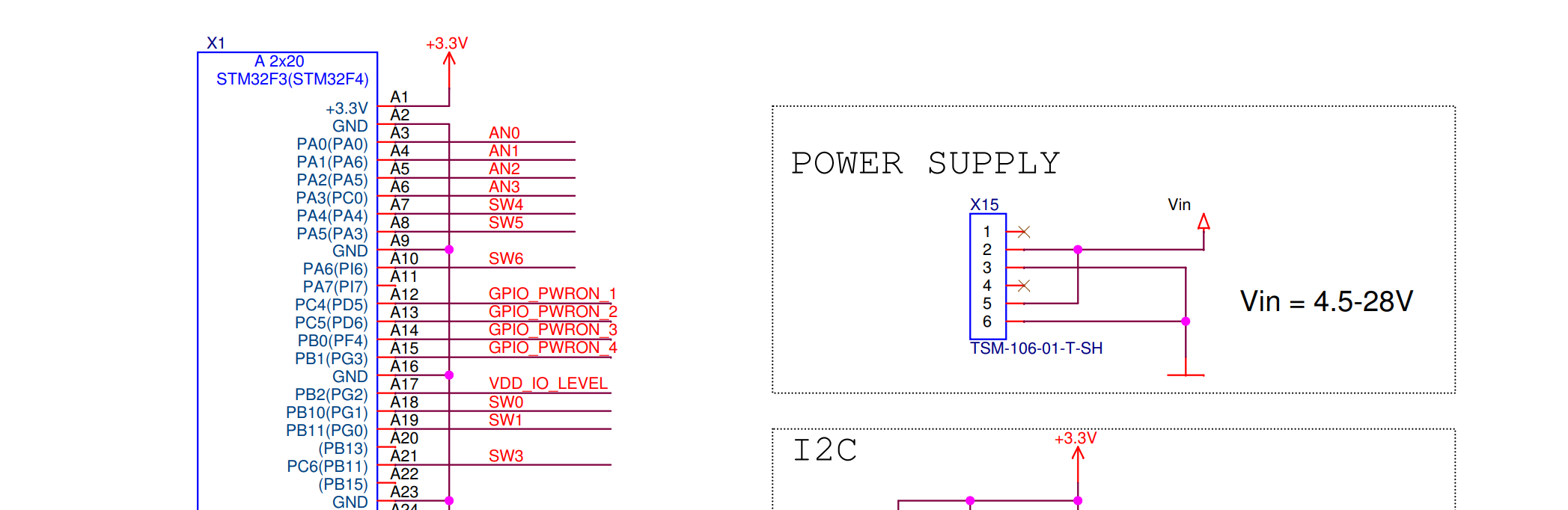
On the actual circuit board, an input is labeled AN4 which is used to enable communication with the radio transmitter.