Home
About Us
News
Products
Documentation
Student
Contact us
Search
contact us
Login
contact us
Category:
Featured Posts
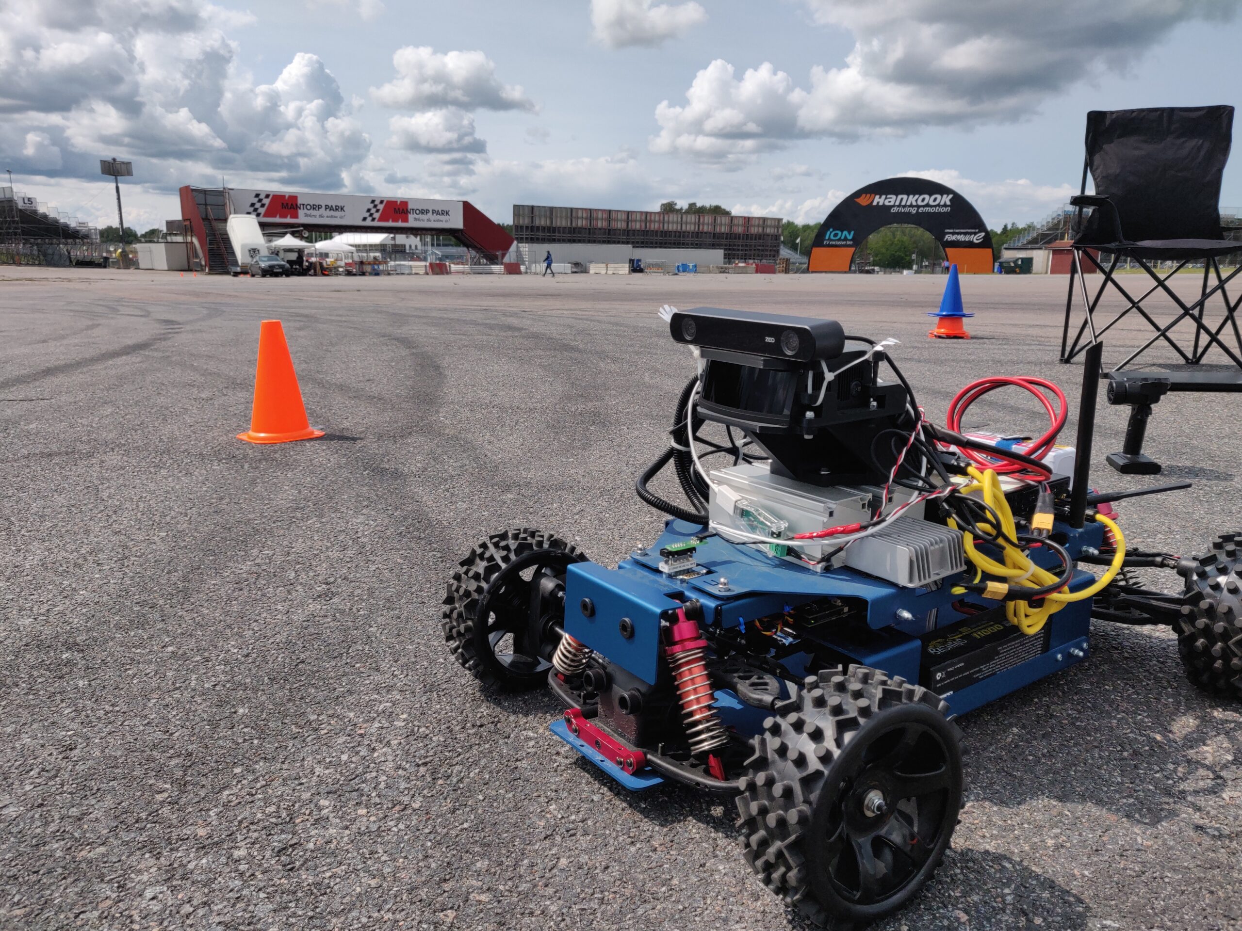
From Simulation to Skidpad: How the CanEduDev Rover is Accelerating LiU Formula Student’s Driverless Ambitions
By Hashem Hashem
Case Study: How Influx’s Use of the CanEduDev Rover Platform is Accelerating Automotive Development and Demo Capabilities
By Mikkel Gerdes
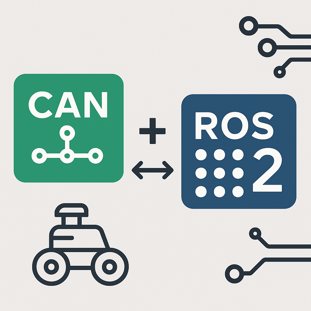
CAN-ROS Integration: What Auto & Industry Need to Know
By Mikkel Gerdes
LiU
Rover platform
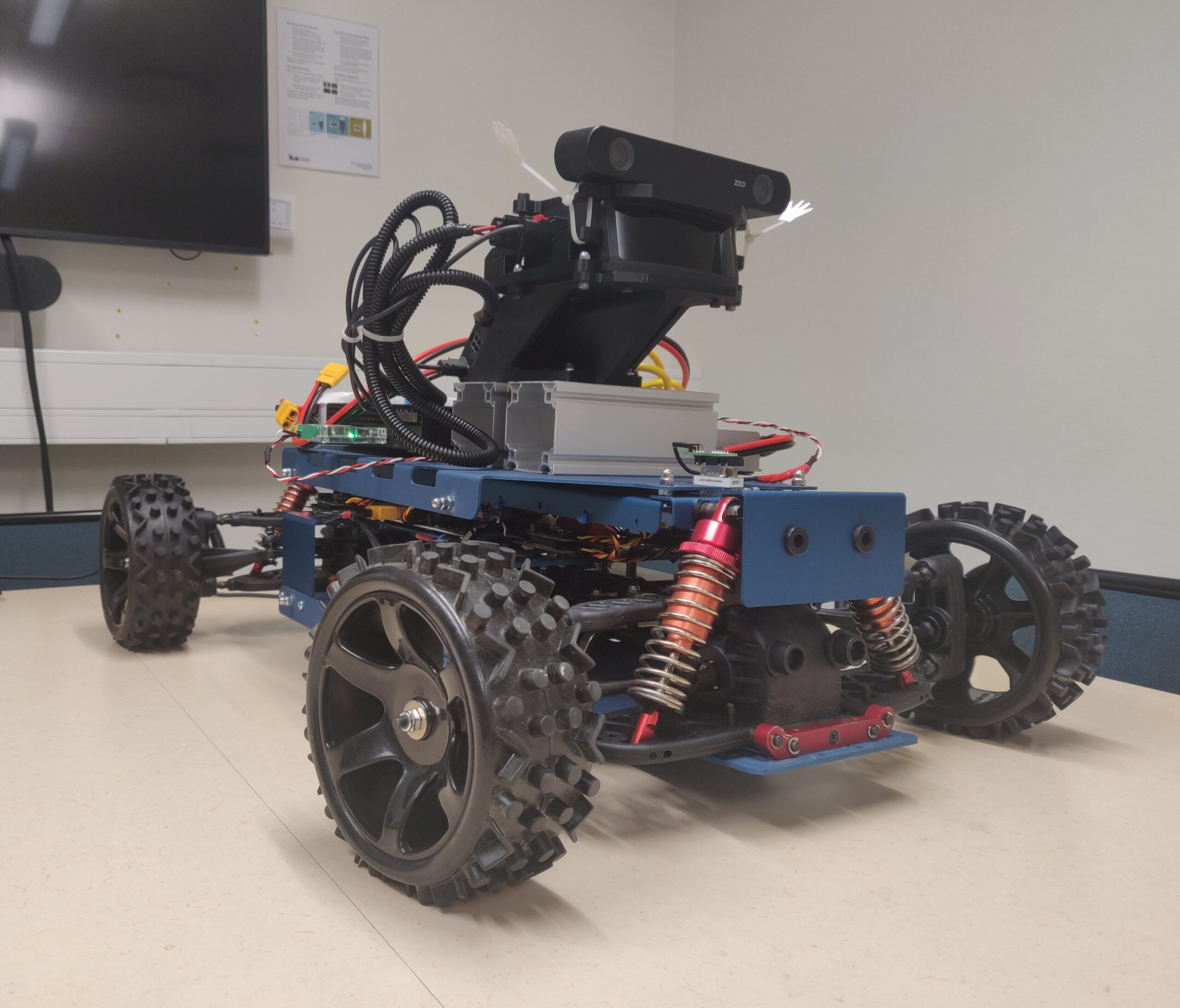
How LiU Formula Student Is Using the CanEduDev Rover to Drive Autonomous Innovation
By Mikkel Gerdes
Autoware
ROS2
Rover platform
SYSTEMS DESIGN
Bringing Autonomy to Life: Autoware Integration with the CanEduDev Rover
By Hashem Hashem
Unlocking the Future with CanEduDev Rover and ROS2 Integration
By Mikkel Gerdes
See All
×
We will email you the product sheet
please provide email
Email Address*
Δ